AG Inverter Drive Control
Setting Up Ageon Variable Speed Drives
The use of external commands is very common in frequency inverters, but do you know which ones, and how to use this function in AG Drive Mini frequency inverters? To use it, we must understand where to connect and which parameters must be changed in the inverter configuration. It is possible to operate the drives using a number of methods that will start and stop the inverter, adjust the speed/direction and more:
1. Direct From Drive Keypad
2. Remote Keypad - See HMI Option
3. External Buttons And Potentiometer (hardwired to inputs)
4. External PLC Signals (hardwired to inputs)
5. Modbus Commands (RS485 data signalling, adaptor required)
AG Drive Line Commands
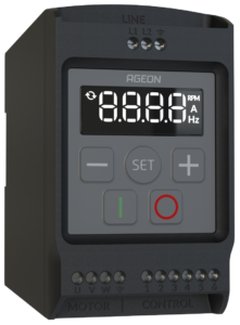
AG Drive inverter commands are selected from the HMI (human machine interface), with On, Off, SET, + and - buttons. All functions are controlled by these buttons, but other functions can be used to control the inverter.
In addition, we also have the inverter's digital inputs that can be configured to obey external sources from the inverter's own control terminals.
Identifying command inputs
So that we can understand how to make the command connections, we must locate each terminal and its functions, the terminals are located on the bottom of the product.
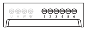
- 10 volt power supply;
- Analog voltage or current input;
- GND;
- DI1 (Digital input 1);
- DI2 (Digital input 2);
- DI3 (Digital input 3).
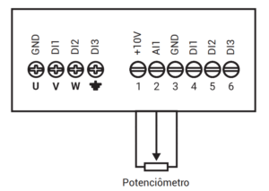
Potentiometer
To use the potentiometer, it is necessary to connect it to terminals 1, 2 and 3. And then change the parameters:
- P301 at 0 = Reference via analog input.
Multispeed
In the multispeed function, it allows the use of two buttons to control 4 different speeds predefined in parameters P201 and up to P204. For this mode, in addition to these parameters, it is necessary to change:
- P301 at 3 = Multispeed reference.
| DI2 | DI3 | Speed |
|---|---|---|
| 0 | 0 | Speed 1 – defined in P201 |
| 0 | 1 | Speed 2 – defined in P202 |
| 1 | 0 | Speed 3 – defined in P203 |
| 1 | 1 | Speed 4 – defined in P204 |
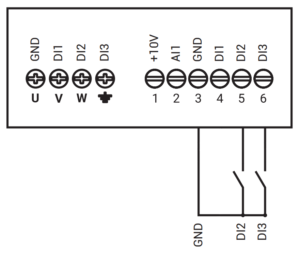
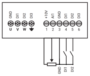
Potentiometer, on/off and direction of rotation
In this operating mode, a potentiometer can be used to control speed, a key to turn the engine on and off and another key to reverse the direction of rotation of the engine, therefore, it is necessary to change the parameters:
- P301 at 0 = Reference via analog input;
-
P302 = 1= Command via digital inputs:
- DI 1 = Activates/Deactivates;
- DI 2 = Direction of rotation.
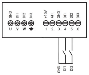
Advance and return
With the forward and return function, two buttons are used where one activates the motor in one direction, while the other, when pressed, activates the motor in the other direction.
-
P302 in 2 = Command via digital inputs:
- DI 1 = Advance
- DI 2 = Return
Inverter Drive Frequently Asked Questions
What are the Main parameters?
AGEON inverters come with various parameters that allow users to configure them according to specific applications. However, some key parameters are important to review, such as:
P11 - Ramp-up time;
P12 - Ramp-down time;
P23 - Motor frequency low limit;
P24 - Motor frequency high limit;
P51 - Overload current;
P301 - Inverter output frequency setting;
P302 - Inverter command mode selection
What is the torque/speed curve?
The torque/speed curve indicates how electric motors vary their torque in relation to speed. It is important to note that at low speeds, the applied torque tends to be lower than the nominal torque. In this regard, it is possible to adjust the torque compensation parameter (P051) to reduce the impacts of this operating condition.
Can I use Modbus communication?
Yes! AGEON inverters have the ability to be controlled via Modbus RTU. It's important to note that the AG DRIVE PRO series has native capability, while the AG DRIVE MINI series requires an adapter.
How can I control the inverter?
AGEON inverters have various control topologies, including through the frequency inverter panel, Modbus RTU communication, remote HMI, some on/off advanced/return topologies, and speed control via multispeed and potentiometer.
Can I use momentary pushbuttons for start/stop control?
All Ageon drives accept hardwired digital inputs. Please note the AG Drive Mini requires a latching circuit to DI1 if you wish to use momentary pushbuttons: